Vesselin VENKOV1, Daniel JOYEUX2, Thomas BUSSON1, Xavier DUPONCHEL2, Clifford CHINAYA2,
1 Promat, Vernouillet (78540), France 2 Efectis, Saint-Aubin (91193), France
ABSTRACT
The aim of this study is to evaluate the residual properties of reinforced concrete in tunnels after HCM (Majorated Hydro Carbon) and ISO type fire incidents lasting 120 minutes, where the concrete has been either protected by protective boards or by addition of polypropylene fibres.
Subsequent to a number of major fire incidents over the last twenty years, the fire resistance of tunnel structures has been revised and increased in a number of countries, largely regarding safety aspects during the incident. The aim of this investigation is to evaluate the residual characteristics of concrete structures after an incident, notably in terms of their durability (compression, porosity, carbonation and chloride diffusion) and covering different solutions in use, in order to provide project managers and clients with clarification regarding the impact of design choices in the event of an incident affecting the structure (damage, structural reinforcement, loss of use, etc.).
The conclusions presented in this report are the result of a two years test campaign.
Two commonly used types of solution, designed with respect to the CETU's (French technical centre for tunnel) technical guidelines, have been tested:
- One solution involving the addition of a protective layer to the concrete structure. HCM (and RWS) certified fire resistant boards have been used to protect concrete slabs.
- Another solution involving the addition of polypropylene fibres to the concrete used for the slabs.
The analysis of the development of the concrete's residual properties after a fire incident was completed after subjecting them to different thermal conditions:
- A standardised ISO 834 curve fire resistance test [1] over a period of 120 minutes, simulating a moderate or severe fire.
- A HCM curve fire resistance test [2] over a period of 120 minutes, representing an extreme fire incident involving a large and combustible payload (notably HGV) which occurrence is probable in a tunnel duration of use.
KEYWORD: fibre reinforced concrete, passive fire protection, ISO 834 Standard fire, Hydrocarbon Modified (HCM) fire curve, durability properties, mechanical properties.
1 INTRODUCTION
The testing program was designed to compare the performance developments of "standard" concrete to which a passive fire protection system has been added with that of fibre reinforced concrete (with mono-filament polypropylene fibres), to which no protection system has been added, subjected to two types of thermal conditions, ISO 834 based to EN 1363-1 [3] or HCM based on the CETU guidelines [4]. The detailed results of this series of tests are provided in the report [5].
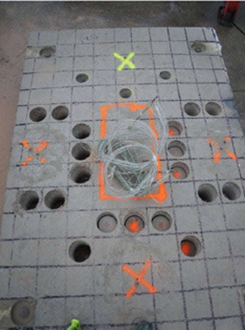
Outside of the direct measurements taken during the fire tests on the different test subjects (temperatures, observations of any thermal instability phenomena, etc.), the degradation of the concrete as a result of the fire tests was assessed by a number of tests to demonstrate the durability and the mechanical properties of the concrete completed after a one month cooling and settling period.
Six slabs were casted (3 in fibre reinforced concrete and 3 in standard concrete). Two slabs, one of each type, were used as a control to compare the variations to the different parameters to be measured after heating.
The other 3 slabs were subjected to the fire resistance test without a physical load. The thermal programs applied to the various units are provided in table 1. One slab (standard concrete + protection) was subjected to two tests, with a period of one month between, under two different sets of thermal conditions (ISO 834 followed by HCM). In this case, the protective boards were replaced after the first test to simulate repair work.
The thermal programs applied to the various units are provided in table 1. The standard concrete slabs were protected with fire resistant boards qualified for these kinds of conditions.
Table 1. The fire tests classified by concrete type and slab number.
|
Slab N° |
D1 |
D2 |
D3 |
D4 |
D5 |
D6 |
|
Concrete |
Fibre |
Fibre |
Standard |
Standard |
Fibre |
Standard |
|
Protection |
No |
No |
X |
X |
|
|
|
ISO 120 min |
X |
No |
X |
No |
Control not tested |
Control not tested |
|
HCM 120 min |
No |
X |
X |
X |
|
|
The properties of the concrete used to make the test subjects are those of C30/37 type concrete (BPS XF1 C30/37 350 kg CEM II/A-S 42.5N D16 S3 Cl 0.4 using siliceous aggregate). The same composition was used for the standard and fibre-reinforced concrete with the addition of 2.05 kg/m3 of propylene fibre to the latter at the production site. Samples (cores) were taken from each of the slabs after the fire tests. These samples were used as the subjects for the tests to determine the mechanical and durability properties of the concrete after the fire incident:
- Porosity accessible to water measurement,
- Chloride transport measurement,
- Accelerated carbonation measurement tests.
- Resistance to compression tests
- Sonic measurement tests
2 FIRE RESISTANCE TESTS
The test slabs each measure 2300 x 1520 x 200 mm. The "standard" concrete slabs were protected with fire resistant boards (35 mm thick) qualified for these types of conditions.
2.1 ISO 120 minute fire test [1]
The D1 (in fibre reinforced concrete) and D3 (protected) slabs were tested under standardised ISO 834 thermal conditions. A very slight spalling on the underside of the unprotected slab was observed during the tests.
Table 2. ISO fire tests - Temperatures at various depths inside the concrete slabs.
|
|
Temperatures (°C) min and max measured - ISO 834 test |
|||||||
|
Slabs |
D1 Fibre-reinforced |
D3 Passive protection |
||||||
|
Time [min] |
60 |
120* |
60 |
120* |
||||
|
Distance to exposed face |
min |
max |
min |
max |
min |
max |
min |
max |
|
180 à 200 mm |
56 |
80 |
82 |
92 |
20 |
21 |
29 |
30 |
|
150 à 170 mm |
62 |
88 |
92 |
104 |
20 |
22 |
31 |
34 |
|
120 à 140 mm |
80 |
100 |
104 |
120 |
22 |
25 |
36 |
41 |
|
90 à 110 mm |
96 |
112 |
120 >150 |
180 >220 |
26 |
32 |
44 |
52 |
|
60 à 80 mm |
110 |
180 |
210 >240 |
320 330 |
34 |
46 |
56 >65 |
68 >80 |
|
30 à 50 mm |
210 |
350 |
370 390 |
530 540 |
50 |
68 |
72 >83 |
86 >100 |
|
0 à 20 mm |
440 |
920 |
620 |
1010 |
76 |
120 |
88 104 |
164 190 |
|
150 - 300°C |
|
300 - 600°C |
|
> 600°C |
- If higher temperatures are measured during the cooling phase, the value mesured is given in superscript. The temperature recording was stoped 155 minutes after the start of the test. In case of the maximum temperature have not been reached, we indicated ">Tfin". Tfin is the maximum temperature recorded.
2.2 HCM 120 minute fire test [2]
The D2 (fibre reinforced concrete), D3 end D4 (protected) slabs were tested under HCM thermal conditions. A slight spalling on the underside of the unprotected slabs was observed during the tests. Remember that, for the D3 slab, a first ISO test was carried out, then before the HCM test, the protective boards were replaced.
Table 3. HCM tests – Temperatures at various depths inside the concrete slabs.
|
|
Temperatures (°C) min and max measured - HCM test |
|||||||||||
|
Slabs |
D2 Fibre-reinforced |
D3 Passive protection |
D4 Passive protection |
|||||||||
|
Time [min] |
60 |
120* |
60 |
120* |
60 |
120* |
||||||
|
Distance to exposed face |
min |
max |
min |
max |
min |
max |
min |
max |
min |
max |
min |
max |
|
180 à 200 mm |
68 |
76 |
80 |
89 |
20 |
21 |
31 |
33 |
20 |
20 |
30 |
32 |
|
150 à 170 mm |
74 |
88 |
90 >115 |
104 >140 |
21 |
23 |
33 |
37 |
20 |
22 |
32 >58 |
36 >64 |
|
120 à 140 mm |
88 |
108 |
106 >160 |
145 >200 |
24 |
28 |
39 |
47 |
23 |
27 |
38 >68 |
45 >75 |
|
90 à 110 mm |
100 |
130 |
170 230 |
250 >300 |
30 |
38 |
50 80 |
61 87 |
29 |
36 |
48 >76 |
58 84 |
|
60 à 80 mm |
150 |
260 |
300 >350 |
450 475 |
42 |
52 |
68 92 |
86 110 |
40 |
52 |
64 89 |
79 109 |
|
30 à 50 mm |
320 |
600 |
540 560 |
820 |
58 |
72 |
92 125 |
116 135 |
56 |
70 |
86 108 |
104 120 |
|
0 à 20 mm |
780 |
1300 |
960 |
1300 |
80 |
120 |
130 150 |
245 255 |
76 |
96 |
116 134 |
188 212 |
|
150 - 300°C |
|
300 - 600°C |
|
> 600°C |
- If higher temperatures are measured during the cooling phase, the value mesured is given in superscript. The temperature recording was stoped 155 minutes after the start of the test. In case of the maximum temperature have not been reached, we indicated ">Tfin". Tfin is the maximum temperature recorded.
3 TESTS TO DETERMINE CHANGES TO CONCRETE DURABILITY PROPERTIES
3.1 Measurement of concrete water porosity
Porosity measurement tests were completed on slices of the cores taken from the control and "fire- tested" slabs. The porosity tests were completed on the lower half of the slab's thickness.
3.1.1 Fibre reinforced concrete
For the fibre reinforced concrete, a significant increase in porosity was observed, from 18% to 22% or as much as 24% on the tested samples.
These measurements show that at similar depths inside comparable fibre reinforced concrete, the porosity increases in relation to the intensity of the thermal conditions to which they have been subjected.
The segmentation of the tests over different depths of the cores shows that, in general, porosity accessible to water is reduced in direct relation to the distance from the fire.
Generally speaking it was observed that porosity accessible to water is affected over at least half of the thickness (10cm) of the fibre reinforced concrete slabs, for all of the thermal conditions which were applied.
For information, according to the general durability indicator classification proposed by the AFGC (French association of civil engineers) performance approach guide [6], a difference of 2% in porosity is sufficient for a structure initially considered to have average durability to be reclassified as being of low durability.
3.1.2 Standard Concrete
Porosity tests on samples taken from the protected slabs did not show any changes to porosity after the tests ISO120 + HCM 120.
Figure 1: Results of porosity accessible to water tests in relation to the core depths.
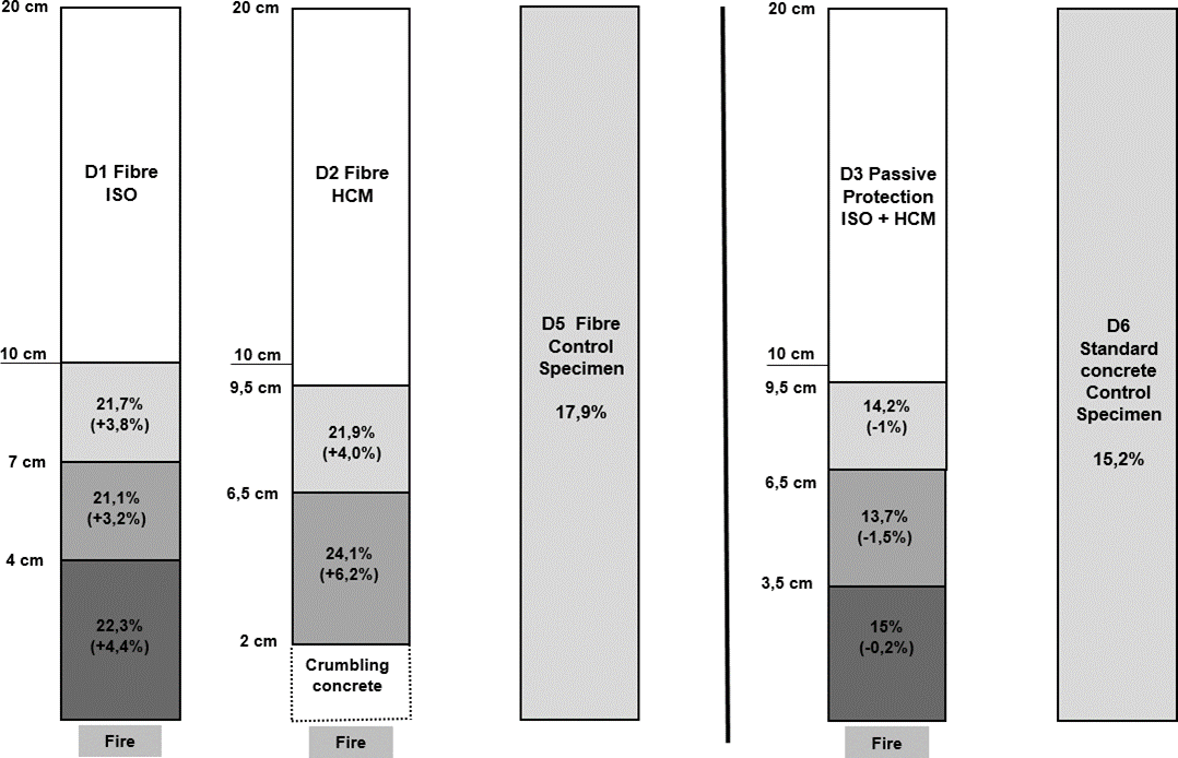
These measurements show that the porosity of the fibre reinforced concrete increases by 4% to 6% whilst the porosity of the protected concrete remains unchanged.
3.2 Measurement of chloride transport under a variable state
Apparent chloride diffusion coefficients (Dapp) were measured for slices of core samples taken from the slabs according to the standard XP P18-462 [7]
3.2.1 Fibre reinforced concrete
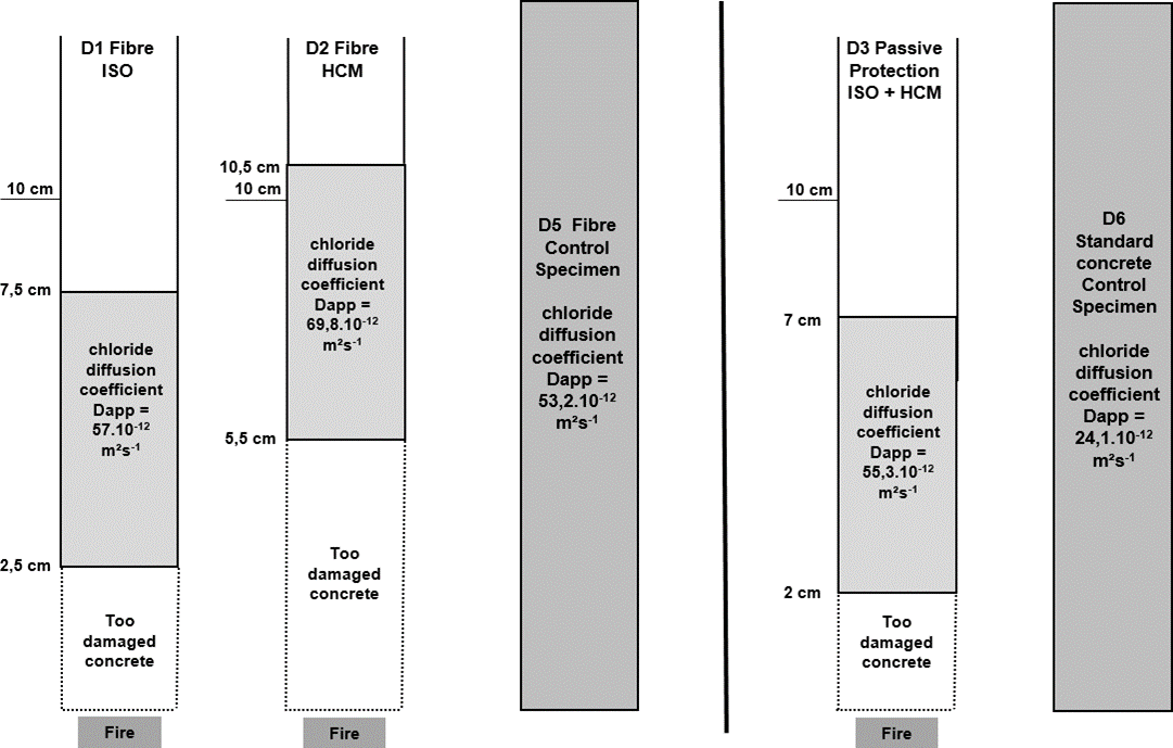
All of the thermal conditions applied to the fibre reinforced concrete resulted in an increase to chloride penetration. The penetration test on the D1 slab, which was only subjected to ISO fire conditions, used a sample that had been located nearer to the fires than those of the D2 slab (20-30mm rather than 50- 55mm). In spite of this, the Dapp increase for this slab (D1) was relatively limited (< 10%).
This increase was much more significant for the slab which had been subjected to HCM fire conditions (> 30%). Regarding the test sample location along the length of the cores, these results indicate that the fire conditions affected the chloride penetration resistance properties of the fibre reinforced concrete up to at least half of the thickness of the slabs.
3.2.2 Standard Concrete
Despite the absence of any physical degradation to the material as a result of the application of the protective boards during the fire tests, the intrinsic chloride penetration properties of the standard concrete were changed. The Dapp measured for Slab D3, subjected to ISO+HCM fire conditions, is higher than that measured for the control standard concrete slab (D7) > 100%.
Though this slab was subjected to 2 fire tests, the results show a significant increase of the Dapp. This increasing is surprising in view of the maximum temperatures measured in these slices of slabe during the tests (~ 150 to 200°C).
Figure 2: Results of chloride penetration tests in relation to the core depths.
Consequences: The depassivation of the armatures, and the subsequent initiation of corrosion, begins when the carbonation or chloride penetration front passes the "exterior concrete layers" and reaches the first armature level. This means that the concrete's transport properties (permeability and diffusion coefficient) will play a key role in the evaluation and forecasting of its durability and life-expectancy.
In the event of armature corrosion the transport of water, carbon dioxide, oxygen and chloride, where present, will come into play. Generally speaking, durability is often related to the material's ability to resist the penetration of aggressive agents.
3.3 Accelerated carbonation tests (XP P18-458 modified)
The accelerated carbonation tests have been performed according to XP P18-458 [8].
This test involves subjecting a test sample, with one of its surfaces having been part of the slab's exterior surface, exposed to a 1% concentration of CO2 for a period of 1 month after which the carbonated depth time is measured by phenolphthalein reaction.
Note: For the control concrete 2cm of the exterior surface was excluded from the test. However, considering that the slabs were intended to be homogeneous over their thickness, the exclusion of the exterior surface will not undermine the results.
3.3.1 Fibre reinforced concrete
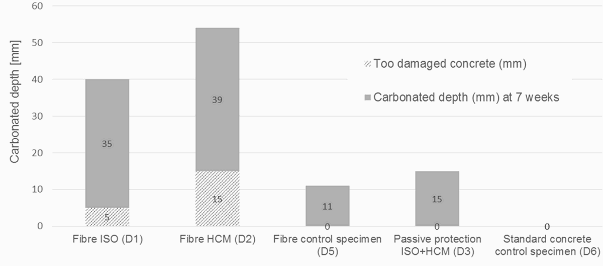
It was observed that the control fibre reinforced concrete slab presents a carbonated depth of 11mm after 7 weeks of exposure to a 1% concentration of CO2.
After 7 weeks of exposure, the carbonated depths measured on the fire-tested fibre reinforced concrete slabs were 3 to 4 times higher than those measured on the control; achieving values between 35 and 42mm, in addition to the thickness of the damaged exterior surface.
These measurements demonstrate that modification to the porous structure of the material are the result of the thermal conditions up to a significant depth (40 to 67mm).
3.3.2 Protected concrete
The protected standard concrete slab that was subjected to ISO+HCM fire conditions (D3): 15mm of carbonation depth was measured after 7 weeks of exposure.
Whilst the integrity of the protected standard concrete has not been visually affected, this measurement shows that modification to the porous structure of the material are the result of the thermal conditions in spite of the application of protective boards. However the thickness in question remains relatively minor (15mm) with regard the two tests carried out.
Figure 3: Carbonated depth (CO2 1% concentration) for fiber reinforced concrete slabs and protected slab after 7week exposure.
4 TESTS TO DETERMINE CHANGES TO THE MECHANICAL PROPERTIES OF CONCRETE
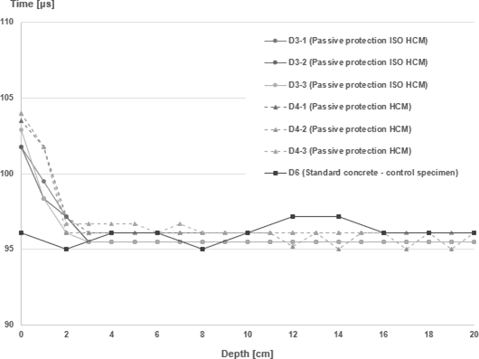
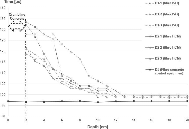
4.1 Sound velocity measurement
We used a direct method with sensors placed opposite each other; the sound wave was transmitted across the whole of the sample thickness. The sensors were placed radially and evenly distributed over the sample. The time taken for the sound to cross the sample was measured for 1cm increments across its thickness. A gradient of this value is observed on the damaged sections, this value becomes constant for undamaged sections.
4.1.1 Fibre reinforced concrete
The sound velocity measurements for this type of concrete provided the following results:
- The surface area of the concrete was observed to be damaged up to a thickness of 2 to 3 cm
- The sound velocity measurement shows an impact on the properties of the concrete slab up to 10 to 12 cm (ISO) and up to 14 cm for the HCM samples. Almost the whole of the fibre concrete cores are therefore affected by the thermal conditions, especially for the HCM fire conditions.
4.1.2 Protected concrete
For the concrete slabs with fire protection boards, the concrete remains cohesive throughout its thickness and degradation to the properties of the concrete are limited to the 3 cm of the base of the slab. The results of the slab exposed to HCM test and that exposed to ISO and HCM (with replacement of the protective board) were similar.
Figure 4: Sound velocity test measurement results for samples taken from fibre reinforced and standard protected concrete slabs.
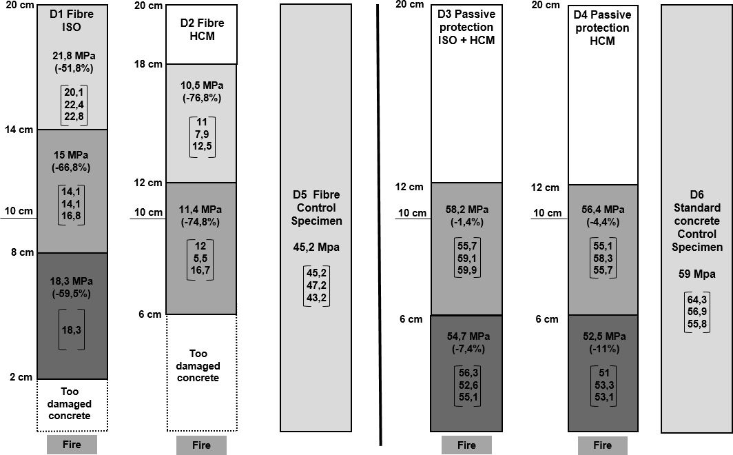
4.2 Resistance to compression
To qualify resistance to compression in relation to the distance from the exposed surface, 6cm long samples were made using the cores taken from the slabs. The resistance to compression measurements were than compared with those of samples taken from the control slabs.
4.2.1 Fibre reinforced concrete
For the fibre reinforced concrete, the results show that there is a significant degradation to the slab exposed to HCM fire conditions (D2). In these conditions, it was observed that the concrete's resistance to compression falls by more than 70% over at least 15cm of thickness. For the slab exposed to ISO fire conditions, there is a lesser fall, but it remains significant, with resistance to compression measurements between 50% and 70% of those taken from the control slab.
4.2.2 Protected concrete
For the concrete with protective boards, the results show only a small change (-10% approx.) which is concentrated over the first 6 cm. We noted that the residual physical resistance of the fibre reinforced concrete slab is significantly reduced, whilst that of the standard concrete slab with protective boards is only slightly affected.
Figure 5: Resistance to compression test results
5 CONCLUSIONS
As indicated in the introduction, the fire tests have been carried out without load. The decision not to load the concrete slabs was initially stated. The goal was to make a preliminary comparison of both protections, so that we can observe and quantify the main differences. On the other hand, it would have been difficult to apply loads to reproduce realistic stress state in the slabs considering the size of the slab and the simultaneous testing of several slabs on the furnace.
However, the slabs were exposed on one side (underside), so a thermal gradient occurs in the slab. The concrete close to the fire is subjected to important thermal expansion and it is constrained by the colder zones. This causes compression stresses on the exposed face while the colder zones are tensed. As a consequence, the concrete may have cracks in depth. The results have to be balanced by considering that phenomenon.
The next step of that study should be to add a representative loading of the concrete slabs in order to assess the impact of the “thermal cracking” on the results or to repeat the tests with standard concrete without protection.
Observation for fibre reinforced concrete
When the polypropylene fibres melt, this leads to a logical increase in the concrete's water porosity; which is a general indicator of the durability of concrete. Consequently, when this type of concrete is exposed to a moderate or intense fire, its durability properties are significantly degraded to a significant depth (more than 10cm).
In general this study has provided an estimate of the depth to which the concrete is physically damaged in relation to its exposure to fire. The results have shown that the physical properties of concrete may be affected to a significant depth (more than 16cm).
In summary, we have observed that the exposure of these types of concrete to ISO or HCM type fire conditions leads to:
- A total degradation of the concrete over the exposed surface area (loss of 5 to 25mm of material thickness),
- A significant fall in the residual physical resistance after cooling phase (up to -70% for a depth of 15cm),
- An impact to durability properties over more than half of the slab thickness.
All of these results are obtained in a specific testing configuration, without loading the slab. Few references exist on literature with so detailed analysis and results. However, their observations, as given in [10] and [11], are similar in term of spalling but do not confirm the significant fall in the residual physical resistance after cooling. The work Gaweska Hager [11] during his PhD thesis observed for high performance concrete with fibers a larger reduction of properties compared to the Eurocode law (EN1992-1-2) that is generally used for structural fire design. However these results were less pronounced than the current results. Thus, further research work to confirm the current results are necessary.
Protected standard concrete
The protective boards more effectively maintained the integrity of the standard concrete slabs. We observed that:
- The integrity of the concrete was maintained.
- Modification to the intrinsic properties of the material were limited to the first few centimetres of the surface area exposed directly to the fire
- The effect of the heat has had little impact on the porosity of the concrete. The accelerated carbonation tests have shown that only the first few cm of the concrete were affected. Only the chloride penetration measurements show that the protected concrete was damaged at any greater depth by the exposure to fire.
- The degradation of the concrete's physical resistance far less than for fibre reinforced concrete. Only the first few centimetres are affected, with a loss of residual resistance of about 10%.
Structure repairs and maintenance
Consequently, in the event of an incident inside a tunnel where the structure which was directly exposed was made from fibre reinforced concrete, it would be advisable to consider the residual durability of the exposed surfaces, especially in terms of their loss of physical resistance. Considering the results of these tests, it would be advisable to verify the depth of the degradation of the concrete and possibly also verify the durability of the structure itself. Sizeable purges of fibre reinforced concrete may also be necessary, in order to return to a "safer" concrete, leading to longer closures to the structure and increasing the costs of renovations. Where standard concrete with protective boards is used, simply replacing the protective boards would be sufficient. Surface protection for added durability could be installed after more serious fire incidents.
6 REFERENCES
- Chinaya C. “Fire test report - ISO fire test”, EFR-14-J-000588A- EFECTIS- France – 2015
- Chinaya C. “Fire test report - HCM fire test” EFR-14-J-000588B – EFECTIS- France 2015
- EN 1363-1 “Fire resistance test” part 1 “general requirements’ – 6 March 2013
- Passive Fire Protection systems : justification of performance for road tunnel structures – CETU – March 2017
- Boisbouvier F. « Caractérisation des bétons de dalles incendiées – Sté Promat », CEREMA – Lyon, France 2016 -
- Scientific and technical documents, a guide for the implementation of a performance related and predictive approach based on durability indicators, AFGC July 2004
- XP P18-462 - Test on concrete - Accelerated migration test of chloride ions under non- stationary conditions – 2012-07-07
- XP P18-458 - Concrete - Gas permeability test on hardened concrete – 2008-12-17
- EN 1992 “Design of Concrete structures” part 1-2 General rules- Structural Fire Design
- YERNAK N. 2015. “Comportement à hautes températures des bétons additionnés de fibres. ” Thèse de doctorat, Université de Cergy-Pontoise.
- Hager, I. 2004. “Comportement à Haute Température Des Bétons à Haute Performance - évolution Des Principales Propriétés Mécaniques.” Thèse de doctorat, Ecole Nationale des Ponts et Chaussées et l’Ecole Polytechnique de Cracovie.

Promat Technical Support
Contact our technical support team with your questions on passive fire protection solutions, our products and systems or installation advice...

Technical Documentation
Find the product datasheets, system brochures, Declarations of Performance, installation manuals and other documents you need to get the job done.