The Promat brand offers a variety of products besides PROMATECT® fire protective construction boards or fire-rated glass of the PROMAGLAS® range. Few people know that the company also distributes intumescent paints, mortars, penetrations and sealing systems to meet the challenges of the 21st century and ensure full architectural fire protection. The sealing solutions described in the article are classified according to European Standards, and all products have European Technical Approval (ETA) so there are no restrictions for their application in EU countries.
Penetration seals
Modern architectural fire protection is based on sub-dividing buildings into fire compartments, in other words, the building must be segmented vertically and horizontally into fire compartments of various dimensions. Surfaces bordering fire compartments must prevent fire and smoke penetration, which can be achieved by fire- stopping structures. It is extremely important to ensure the continuity of these protection planes. Since modern buildings include electrical and mechanical pipe systems similar to the human vascular system, the breakthrough of these protective planes cannot be avoided. These holes (penetrations) have to be closed (sealed) by fire protective solutions tested according to the above-mentioned European Test Standard (EN 1366-3) and classified according to the EN 13501-2 Standard – no other type of classification may be applied. This article aims to raise awareness of these issues and describe the certified Promat solutions. Due to the provisions of the classification standard it is not as easy as it seems at first to choose and provide suitable penetration seals.
Local legislation dealing with fire spread protection offers numerous solutions for fire-stopping pipe penetrations, e.g. it is obvious that the penetration of a combustible pipe or a metal pipe has to be sealed differently. Moreover, it has to be taken into consideration whether the penetrating pipe is insulated or not, and the system to be applied depends on the material quality of the insulation. The EN 1366-3 Test Standard covers a lot of these criteria. The table below contains a simple list of test arrangements depending on each pipe type:
| Metal pipes | Plastic pipes |
| side by side, linearly arranged pipes | pipe closure systems |
| bundles of pipes | other closures |
| insulation: non-combustible or combustilbe | insulation |
| pipe diameter and pipe wall thickness | pipe within pipe systems |
| pipe end configuration | pipe end configuration |
| material of the pipe | material of the pipe |
Due to the limitations of the article’s scope, we will cover only materials and diameters of pipes, wall thicknesses, insulation and pipe end configurations. Other topics will be explained in subsequent articles.
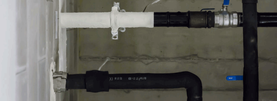
Insulated metal pipes
Regardless of the combustibility of the insulation, the EN 1366-3 Test Standard distinguishes between:
- insulations passing through without interruption (sustained insulation, marked with S);
- interrupted insulations (marked with I);
- pipes are insulated in their entire length (continued insulation, marked with C) or;
- insulated locally, only in the vicinity of the penetration (local insulation, marked with L).
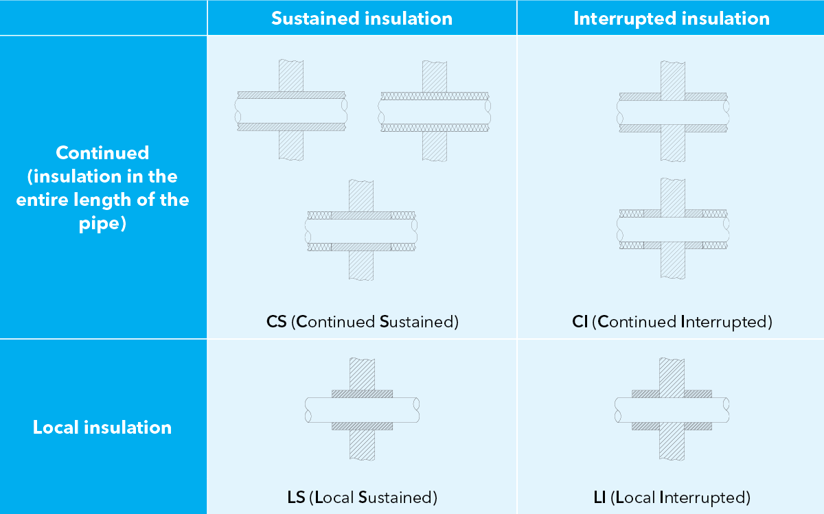
This can be better understood by looking at the table.
Altogether there are four possible cases depending on the arrangement of pipe insulation in the penetration:
- CS (Continued Sustained): the entire length of the pipe is insulated and the insulation passes through the penetration’s cross section;
- CI (Continued Interrupted): the entire length of the pipe is insulated but the insulation is interrupted in the penetration;
- LS (Local Sustained): the pipe is insulated only in the vicinity of the penetration and the insulation passes through the penetration’s cross section;
- LI (Local Interrupted): the pipe is insulated only in the vicinity of the penetration and the insulation is interrupted in the penetration.
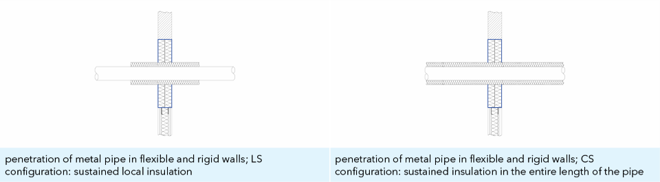
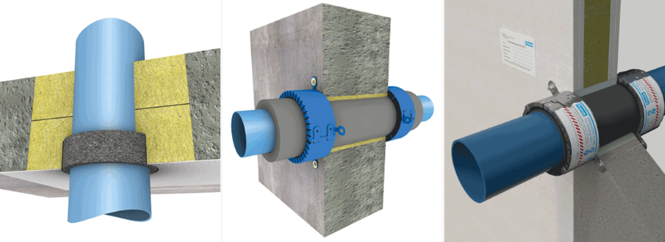
The insulation – depending on its relevance to fire classification – might be used in the penetration (as part of the system) or it might form the penetration by itself, although additional insulation might be required, and this is not shown in the drawing. Manufacturers’ technical manuals include the above-stated details. With the help of mineral wool, metal pipes can pass through soft penetrations by using PROMASTOP®-CC coating with non-combustible insulation in LS or CS configurations (i.e., sustained insulation locally or over the entire length of the pipe).
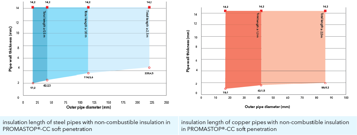
Important note! When applying the soft penetration seal of metal pipes, it must be taken into consideration that in case of fire the metal pipe will stretch due to the significant heat expansion; the weight of the pipe due to stretching cannot burden the cross section of the soft penetration, as it might damage its integrity. This can be avoided by using a non-combustible insulation band of specific length and quality (local insulation) installed on the pipe, that is why metal pipes usually have insulation when passing through soft penetrations. The diagrams show the minimum required length of the typical mineral wool compartment insulation, depending on the material and diameter of the metal pipe and thickness of the pipe wall.
Pipe wall thickness and insulation
Generally speaking, shorter compartment insulation is suitable for metal pipes with a smaller diameter, smaller wall thickness and lower thermal conductivity: with PROMASTOP®-CC soft penetrations of metal pipes with low thermal conductivity (λ ≤ 58 W/mK), pipe wall thickness 2,0 mm – 14,0 mm and pipe outer pipe diameter up to 42,0 mm require a non-combustible local insulation total centered penetration length of 500 mm; steel pipes with larger pipe wall thickness or outer pipe diameter need a minimum of 1000 mm long local insulation. According to the EN 13501-1 Standard, the reaction to fire classification of the local insulation in PROMASTOP®-CC soft penetration is a minimum of A2-s1, d0 or A2L-s1, d0; its melting-point is a minimum of 1000°C, bulk density is between 40 and 150 kg/m³, and thickness is between 30 and 100 mm. (Warning: this data is not the material characteristics of the mineral wool boards forming the soft penetration itself, as these are covered by a special provision; the thickness in the referred penetration is 1 x 50 mm, 1 x 80 mm or 2 x 50 mm, and the bulk density is minimum 140 kg/m³). The minimum required local insulation length for copper pipes with larger thermal conductivity (λ ≤ 380 W/mK), pipe wall thickness up to 14,2 mm and pipe outer diameter up to 42 mm, is 1000 mm; copper pipes with a larger outer pipe diameter (up to 88 mm) need a minimum of 2000 mm long local insulation.
Not only the Promat solutions require this complicated system, but all producers are expected to present the required insulation length in this way, according to the Test and Classification Standard.
Pipe end configuration
According to the EN 1366-3 Test Standard, four possibilities are determined based on the design of the metal or plastic pipe ends passing through the tested penetration, depending on whether the end of the tested pipe was closed inside and outside of the furnace (Capped, marked C) or was open (Uncapped, marked U).
| Test condition | Pipe end configuration | Type of pipes | |
| Oriented inside (in furnace) | Oriented outside (outside the furnace) | ||
| U/U | uncapped | uncapped | plastic: rainwater, ventilated sewage (drainage channel) |
| U/C | uncapped | capped | plastic: unventilated sewage; gas; drinking water, heating water (supply channel); metal: non fire-resistant suspension/coupling systems, waste disposal shafts made from pipes |
| C/U | capped | uncapped | metal: fire-resistant suspension/coupling systems |
| C/C | capped | capped | / |
The behavior of the specimen during the test is fundamentally determined by the design of the pipe end: the pressure and flow of hot gases are different in (an open) pipe that is in contact with the atmosphere than in a capped pipe, so when choosing the suitable fire protection solution the proper pipe end configuration must be taken into account as well, and not just the usual EI XX fire classification. Certainly all readers have already seen the U/U or U/C mark in the fire classification of a modern fire collar, which was explained above (i.e. a pipe open on both ends has a U/U configuration, which is the worst-case scenario from a fire protection point of view, so all solutions with this classification are suitable for any pipe ends).
Let’s take a look at these marks referring to the given installation positions and structural establishments in the classification of fire-stopping collars PROMASTOP®-FC (powder-coated stainless-steel body with intumescent inlay) and PROMASTOP®-FC MD (cut-to-length collar) and PROMASTOP®-W fire-stopping wrap. The pipe end classification may differ in light or solid wall, in a soft penetration or core drilled hole, in wall or floor penetration.
Service support construction
All penetration seals are capable of performing their function as long as they are unharmed, which requires suitable, stable hanging or support. During the test the manufacturer determines the distance of the first service support construction from the surface of the penetration, and this distance must not be increased by applying the penetrations in practice. Pipes must be supported at a ≤ 250 mm distance in a PROMASTOP®-CC soft penetration on both sides of the wall or from the top of the floor to avoid excessive load of the mineral wool boards in the soft penetration. The supporting distance must be checked for each product in the related manual.
What should be taken into consideration?
Finally let us summarize the most important elements you should pay attention to when designing or planning a penetration seal:
- thickness, bulk density, reaction to fire classification and melting point of the mineral wool boards in soft penetrations;
- required thickness of the applied coating;
- length, thickness, bulk density, reaction to fire classification and melting point of the local insulation;
- whether the classified pipe end configuration is suitable for the building position;
- distance of the first suspension/support from the soft penetration.

Online tools
Promat ontwikkelde twee online tools. Met de Selector App vindt u het perfecte Fire Stopping product. De Promat Structural Protection Calculator is geschikt om de beschikbare Promat-oplossingen te vinden voor de bescherming van staal tegen brand.

Technische documentatie
Vind alle product datasheets, prestatieverklaringen, installatiehandleidingen, handboeken, … die u nodig heeft om de klus te klaren.